
The human ear is capable of determining the volume of a sound. It can also tell the difference between two sound sources of varying strengths. Is there, however, a device that can perform the same function? The Sound Sensor is the perfect device to perform these function.This article discusses an overview of the sound sensor module, its working and how to interface the sound sensor with Arduino.
WHAT IS A SOUND SENSOR?
The sound sensor is one of the most prominent sensors used in the electronics system nowadays. A sound sensor detects the intensity of sound and converts it into an electrical signal. This module includes a Microphone, a Peak detector, and an Amplifier. In this converter IC, we use LM393 Op-amp that is highly sensitive to sound. When the sensor detects a sound it is processed and the output voltage signal is provided to the microcontroller for further processing. This module can detect noise levels at a range of decibels at 3 kHz-6 kHz frequencies, approximately where the human ear is sensitive.

This sensor can detect noise levels in DB’s (decibels) at frequencies between 3 and 6 kHz, which is approximately where the human ear is sensitive. To measure the sound level, an android application called decibel meter is available for smartphones.
SPECIFICATIONS
The specifications of the sound sensor include the following
- IC Chip: LM393
- Operating voltage: 3.3V-5V
- operating current: 4-5 mA
- Voltage gain 26 dB (v=6v, f=1khz)
- Sensitivity of the microphone (1khz) :52 to 48 dB
- The impedance of the microphone: 2.2k ohm
- Frequency of microphone: 16 to 20 kHz
- Signal to noise ratio: 54 dB
- Signal output indication
- The output is digital.
- Single-channel signal output.
- With the retaining bolt hole, convenient installation.
- Output low level and the signal light when there is sound.
- Dimension:45*17*9mm
- Weight: 5gm
SOUND SENSOR PIN CONFIGURATION
- Pin1: (VCC) – 3.3V DC to 5V DC
- Pin2 :( GND) – This is a ground pin
- Pin3 :( DO) – This is an output pin
- Pin4: ( A0 ) – Analog output pin

WORKING PRINCIPLE
The working of the sound sensors is similar to that of the human ear. Because the human eye has a diaphragm, the diaphragm’s primary job is to convert vibrations into signals. Whereas in the sensor, the microphone uses the vibration generated and converts it into current or voltage. When the sound signal hits the diaphragm the magnet present within the sensor undergoes vibration, as a result, the current stimulates from the coil.

This converter IC consists of an inbuilt potentiometer to adjust the set point for the sound level. The analogue/digital output pin of the module is connected to the analogue/digital pin of the microcontroller. When the sound level exceeds a threshold value, the LED turns ON, and output sets to low.
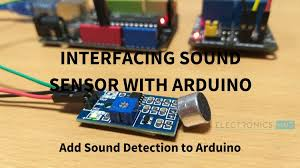
INTERFACING SOUND SENSOR WITH ARDUINO
As the project is about interfacing a Sound Sensor with Arduino, let us see how its done. First of all connect the Sound Sensor to the Arduino and use an LED to detect the sound. As my sound sensor only has a digital output, I’ll just use the Arduino’s digital I/O pins..
COMPONENTS REQUIRED
- Sound Sensor Module
- Arduino UNO
- Relay Module (5V)
- LED
- 1KΩ Resistor
- Connecting wires
- Mini Breadboard

CIRCUIT DIAGRAM

The connections are as follows VCC of the sound sensor is connected to 5 volts of Arduino board, the ground pin is connected to the ground of the breadboard, and the OUT pin of the Sensor to Digital I/O pin 7 of the Arduino board. The negative terminal of the LED is connected to the ground of the breadboard and the positive terminal of the battery is connected to one end of the 1k resistor, the other end of the resistor is connected to the 12th pin of the Arduino board.
Download the Arduino IDE and use the below code.
CODE
| const int ledPin = 12; const int soundPin = 8; int soundVal = 0; void setup () { pinMode (ledPin, OUTPUT); pinMode (soundPin, INPUT); Serial.begin (9600); } void loop () { soundVal = digitalRead(soundPin); if (soundVal == HIGH) { digitalWrite(ledPin, HIGH); Serial.println(“Clap detected”); delay(1000); } else { digitalWrite(ledPin,LOW); } } |
CALIBRATING SOUND SENSOR
To get accurate readings out of your sound sensor, it is recommended that you first calibrate it.
A built-in potentiometer allows you to calibrate the digital output of the module (OUT).You can set a threshold by rotating the potentiometer’s knob. The Status LED will light up and the digital output (OUT) will output LOW when the sound level exceeds the threshold value.
Start clapping near the microphone to calibrate the sensor, and adjust the potentiometer until the Status LED on the module blinks in reaction to your claps.Your sensor is calibrated and is ready for use now.
OUTPUT
After making the connections and uploading the code to Arduino, snap or clap in front of the sensor. You can observe the LED connected to OUT Pin of the sound sensor as well as the Digital Pin 12 of Arduino will be active whenever it detects any sound.

Simultaneously, you can see the output on the serial window of Arduino IDE.

APPLICATIONS OF SOUND SENSOR:
- Security system for Office or Home
- Spy Circuit
- Home Automation
- Robotics
- Smart Phones
- Ambient sound recognition
- Audio amplifier
- Sound level recognition (not capable to obtain precise dB value)
CONCLUSION:
This Blog discusses an overview of how to interface the sound sensor with Arduino. Hope this article helps you to understand the working principle, Interfacing and Applications of sound sensors.